inquiry
Leave Your Message

Top 10 CT on Transformer Types for Global Buyers

Global power networks are entering a demanding investment cycle. The International Energy Agency reports that electricity demand should grow by about 3.4% annually from 2024 to 2026. Its Electricity Grids and Secure Energy Transitions report also estimates that annual grid investment must exceed USD 600 billion by 2030. These pressures increase demand for dependable measurement and protection equipment, including the Ct On Transformer used in substations, industrial panels, renewable plants, and utility networks.

Accuracy matters.

A current transformer is not selected by ratio alone. Buyers must examine accuracy class, rated burden, insulation level, short-time thermal current, knee-point voltage, and installation space. Protection CTs, metering CTs, split-core CTs, bushing CTs, and ring-core designs serve different operating conditions. IEC 61869-2 provides key requirements for instrument transformers, while IEC 60044-1 remains a useful reference for older specifications. Regional certification, frequency, climate, and maintenance practices also affect the final choice.

Small errors compound.

This guide compares ten major Ct On Transformer types for global buyers. It connects technical design with real purchasing decisions, such as a crowded switchgear cabinet, a 33 kV feeder, or a solar inverter’s fluctuating output. Manufacturer datasheets remain essential evidence. So do type-test reports, calibration records, and verified supplier experience. Market reports often simplify product categories, and that can mislead procurement teams. A better assessment considers application risk, lifecycle cost, measurement accuracy, and compatibility with protection relays. Some recommendations may change after site inspection. That uncertainty deserves attention, not concealment.

Top 10 CT on Transformer Types for Global Buyers

What CTs Are and How They Work in Power Transformers

Top 10 CT on Transformer Types for Global Buyers

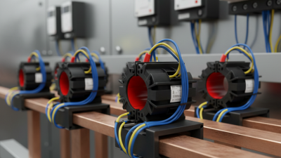
A current transformer, or CT, converts a high primary current into a smaller measurable current. Its secondary circuit feeds meters, relays, and protection systems. In a power transformer, CTs may be wound, toroidal, bushing-mounted, or split-core. Each design fits a different installation constraint. A bushing CT surrounds an insulated conductor inside the transformer tank, while a toroidal CT forms a ring around the current path.

The operating principle is simple. Primary current creates magnetic flux in the core. That flux induces secondary current, commonly 1 A or 5 A. The ratio must match the protection scheme and measurement range. Accuracy also depends on burden, frequency, core material, and lead length. IEC 61869-2 defines key requirements for instrument transformers, including accuracy and insulation performance. IEEE C57.13 provides widely used transformer-instrument standards in North America. Small details matter here.

The U.S. Department of Energy’s 2024 distribution-transformer rule projects major lifetime energy savings from improved transformer efficiency. CT losses are smaller, but poor CT selection can still weaken protection. A saturated CT may fail to reproduce fault current accurately. That mistake can delay relay operation. Engineers should check short-circuit levels, knee-point voltage, insulation class, polarity, and thermal limits. Buyers often focus on ratio and price. That is not enough. Field testing also matters, although test results can be misunderstood when the wiring diagram is incomplete. Always verify the actual transformer design and local grid requirements.

Top 10 CT on Transformer Types for Global Buyers

What CTs Are and How They Work in Power Transformers

A current transformer (CT) reduces a high primary current to a standardized, measurable secondary current, commonly 1 A or 5 A, for protection and metering. The chart shows representative CT applications and calculated transformer full-load currents at the CT location.

Full-load current is calculated using I = S / (√3 × V). The transformer ratings and voltages are engineering examples; the selected CT ratios are representative nominal choices and must be confirmed against fault level, burden, accuracy class, insulation level, and protection requirements.

The Ten Main CT Types Used in Transformer Systems

Top 10 CT on Transformer Types for Global Buyers

The Ten Main CT Types Used in Transformer Systems

Current transformers, or CTs, support measurement, protection, and system control. Their selection affects accuracy, safety, and maintenance.

The ten main types include wound-primary, bar-primary, window, bushing, split-core, core-balance, summation, metering, protection, and multi-ratio CTs. Wound-primary CTs suit lower-current applications and offer flexible ratios. Bar-primary units use a solid conductor for strong fault performance. Window and bushing CTs pass around existing conductors or transformer bushings. Split-core models open around cables, making retrofit work faster. Core-balance CTs detect residual current during ground faults. Summation CTs combine several feeder currents into one output. Metering CTs prioritize steady accuracy under normal loads. Protection CTs tolerate heavy fault currents and preserve relay signals. Multi-ratio CTs provide several usable ratios through selectable taps.

These categories can overlap. A bushing CT may also be a protection CT. That matters during specification reviews. Check ratio, burden, insulation level, frequency, polarity, and secondary current. Common secondary ratings include 1 A and 5 A. Protection designs may also require knee-point voltage and excitation data. Field conditions deserve equal attention. Heat, moisture, vibration, and limited cabinet space can change performance.

A tidy product list can mislead. I have seen installations where the ratio looked correct, but the burden was too high. The result was unreliable measurement. Engineers should compare test certificates, applicable standards, wiring length, and grounding arrangements. Local grid rules also differ. Careful verification remains more valuable than choosing the largest CT.

CT Type Selection by Transformer Rating and Application

Selecting the right current transformer depends on transformer rating, fault level, and operating purpose. A small distribution transformer may suit a ring, window, or split-core CT. Larger power transformers often require bushing, bar, or wound CTs. Protection schemes need high accuracy during faults. Metering circuits prioritize stable performance near normal load.

IEC 61869-2 defines requirements for measuring transformers, while IEEE C57.13 specifies common accuracy and burden practices. These standards should guide the final choice. The IEA’s Electricity 2024 report expects global electricity demand to grow by more than 6% from 2024 to 2026. More generation and grid expansion will increase CT installations, but quantity must not replace correct sizing.

Tips: Check primary current, short-circuit level, burden, insulation class, and installation space. For protection, verify the knee-point voltage and saturation behavior. For revenue metering, confirm the accuracy class at the actual operating range. A residual CT can detect earth faults, while a summation CT combines feeder currents. Split-core designs simplify retrofit work, but they may offer weaker mechanical consistency. This detail is often underestimated.

CT selection can still be imperfect. Real loads change, cables heat, and future capacity may exceed the original design. Review relay settings, test results, and site conditions together. A technically compliant CT can still perform poorly when its burden calculation is incomplete.

Top 10 CT on Transformer Types for Global Buyers - CT Type Selection by Transformer Rating and Application

Practical selection guide for current transformers used with power, distribution, dry-type, renewable-energy and industrial transformers. Ratings and classes below are typical engineering ranges; the final selection must be checked against the system voltage, fault current, relay burden, insulation level and applicable IEC or IEEE requirements.

Rank CT Type Typical Transformer Rating / Application Installation Position Common Primary Ratio Range Typical Secondary Metering or Protection Class Typical Burden Main Selection Advantages Important Design Considerations
1 Bushing Current Transformer
Power Transformer
Medium- and large-power transformers, commonly from approximately 10 MVA upward, including generator step-up and grid transformers. Installed around an insulated transformer bushing or integrated into the bushing assembly. Typically 100/1 A to 3,000/1 A or 3,000/5 A, selected according to rated winding current. 1 A or 5 A Metering classes 0.2, 0.2S or 0.5; protection classes 5P, 10P or PX, subject to the protection scheme. Commonly 5–30 VA for protection or metering circuits. Compact, electrically integrated and suitable for differential, restricted-earth-fault and backup protection. Confirm bushing dimensions, insulation coordination, polarity, knee-point voltage and the available number of cores.
2 Bar-Type CT
MV Distribution
Medium-voltage distribution transformers, feeder incomers and transformer switchgear, commonly from 500 kVA to 20 MVA. A solid primary conductor or busbar passes through the magnetic core and acts as the primary winding. Typically 50/5 A to 2,000/5 A, with dual-ratio versions available. 1 A or 5 A Metering 0.5 or 0.5S; protection 5P10, 5P20 or comparable utility specifications. Typically 5–15 VA. Good mechanical strength, low primary impedance and straightforward installation in metal-enclosed switchgear. Check busbar size, phase spacing, short-time thermal current and dynamic current withstand.
3 Wound-Primary CT
Low-Current Systems
Small distribution transformers, dry-type transformers, auxiliary transformers and control panels where the primary current is relatively low. The primary conductor is permanently wound through the CT core as one or more turns. Typically 5/5 A to 600/5 A; multi-turn designs support low primary currents. 1 A or 5 A Metering classes 0.5, 0.5S or 1.0; protection classes 5P10 or 10P10 where required. Typically 2.5–15 VA. Provides accurate transformation at low primary current and can accommodate a defined primary winding arrangement. Verify primary insulation, conductor heating, terminal clearances and the actual number of primary turns.
4 Window-Type CT
Cable or Busbar
Transformer incomers, cable-connected distribution transformers and low- or medium-voltage switchboards. The complete insulated cable, busbar or conductor passes through a central aperture. Typically 50/5 A to 2,500/5 A; the ratio is determined by the number of primary passes through the aperture. 1 A or 5 A Metering 0.5 or 0.5S; protection 5P10, 5P20 or application-specific equivalent. Typically 5–20 VA. Flexible installation, no direct electrical connection to the primary circuit and suitable for factory or field assembly. Maintain the specified cable position, aperture clearance and conductor centering to avoid measurement errors.
5 Ring-Core / Toroidal CT
Compact Transformers
Compact oil-filled or dry-type transformers, renewable-energy transformers and space-constrained transformer panels. Mounted around a cable, insulated conductor or bushing connection without a conventional wound primary. Typically 100/1 A to 2,000/5 A. 1 A or 5 A Metering classes 0.5, 0.5S or 1.0; protection classes 5P or 10P. Typically 2.5–15 VA. Small footprint, low weight and good suitability for retrofit or densely populated enclosures. Keep the conductor centered and ensure that the core does not saturate under the specified fault current.
6 Split-Core CT
Retrofit Measurement
Existing distribution transformers, commercial transformer rooms, energy-monitoring projects and installations where the primary conductor cannot be disconnected. Clamped around an existing cable or busbar after the circuit has been installed. Commonly 100/1 A to 1,500/5 A; output may also be designed for low-level metering interfaces. 1 A, 5 A or a low-level voltage/current output depending on the measuring system. Usually metering class 0.5, 1.0 or 3.0; generally not preferred for high-speed protection. Often 1–10 VA for conventional secondary outputs. Fast installation, minimal downtime and no need to remove the primary cable. Close the split core fully, keep the mating surfaces clean and avoid opening the secondary circuit while energized.
7 Core-Balance CT
Earth-Fault Detection
Transformer feeders, neutral-earthed systems, motor-transformer feeders and residual-current protection circuits. All phase conductors, and the neutral where applicable, pass through one common core. Often specified by residual current, such as 50/1 A or 100/1 A equivalent, rather than by full-load phase current. 1 A or 5 A Protection or residual-current sensitivity requirements; class selection depends on the relay and fault-current range. Typically 1–10 VA. Detects zero-sequence current directly and can provide sensitive earth-fault protection. Do not pass protective-earth conductors through the core unless the protection design specifically requires it.
8 Protection-Class CT
Differential & Backup
Transformer differential protection, overcurrent protection, restricted earth-fault protection and backup protection on transformers of various ratings. Installed on transformer bushings, cable terminations, switchgear busbars or neutral connections. Selected from transformer full-load current and fault duty; common ratios include 100/1 A, 400/1 A, 800/5 A and 1,200/5 A. 1 A or 5 A IEC-style 5P10, 5P20, 10P10, 10P20 or PX; IEEE protection classes may be specified for North American systems. Typically 10–30 VA, including relay and lead burden. Maintains acceptable accuracy during high fault currents and supports dependable relay operation. Calculate total lead burden, relay burden, saturation margin, knee-point voltage and remanence effects.
9 Metering-Class CT
Energy & Revenue Measurement
Transformer revenue metering, feeder energy monitoring, load management and power-quality measurement. Installed on transformer primary or secondary conductors, switchgear busbars or dedicated metering cores. Typically selected close to the normal operating current, for example 200/5 A, 400/5 A or 800/1 A. 1 A or 5 A IEC-style 0.2S or 0.5S for high-accuracy metering; class 0.5 or 1.0 for general monitoring. Typically 2.5–15 VA. Provides improved accuracy over the declared measurement range and supports precise energy calculations. Choose the ratio so normal load is not far below the accuracy range; never exceed the rated burden or open the secondary circuit.
10 Summation CT
Multiple Feeders
Transformer substations with several parallel feeders, multiple secondary windings or consolidated monitoring and protection circuits. Receives secondary currents from two or more feeder CTs and provides one combined secondary output. Common input combinations include 5+5/5 A or 5+5+5/5 A; output ratio is specified for the connected relay or meter. Usually 1 A or 5 A Metering class 0.5 or 1.0; protection accuracy is selected according to the summated relay scheme. Typically 5–15 VA, excluding the burden of upstream feeder CTs. Reduces wiring to a single meter or relay input and combines currents from multiple transformer circuits. All input CT ratios, phase angles, polarity marks and burdens must be compatible before summation.

Engineering note: CT secondary circuits should be properly grounded at the designated point and must not be left open while the primary is energized. Ratio, insulation level, short-time thermal current, dynamic current, accuracy limit factor and burden should be verified against the transformer nameplate and the applicable project standard.

Global Standards for CT Accuracy, Safety, and Performance

Across wound, bar, and window current transformers, global buyers should treat standards as design requirements. IEC 61869-2 and IEEE C57.13 provide useful reference points, but local grid rules still apply. Metering CTs need stable ratio accuracy. Protection CTs need dependable performance during fault currents. That distinction is critical. A class 0.2 CT may suit revenue measurement, while a protection core needs controlled saturation behavior. Check ratio, rated burden, frequency, accuracy class, and operating temperature before approval. Do not trust a single headline value.

Safety begins with insulation, not paperwork. Review power-frequency withstand, lightning impulse withstand, creepage distance, and enclosure protection. Secondary terminals should be clearly marked and firmly enclosed. Ask for routine test records, type-test evidence, calibration data, and material traceability. For outdoor substations, inspect sealing, corrosion resistance, ultraviolet exposure, and condensation risks. Small details matter. An open-circuited CT secondary can produce dangerous voltage and damage equipment. Installation teams need clear grounding instructions and practical isolation procedures.

Performance depends on the complete measuring chain. Select the core with the relay, cable length, and expected fault level in mind. Compare knee-point voltage, excitation current, composite error, and short-time thermal current. Global compliance is not automatic. Certificates may be valid, yet their scope may not match your project. Field review often reveals overlooked heat, vibration, or wiring constraints. No selection is perfect. A neat specification can still hide a difficult installation.

Comparing CT Types for International Purchasing Decisions

Top 10 CT on Transformer Types for Global Buyers

Comparing CT types requires more than checking ratio and price. A wound-core CT suits low-current applications and offers flexible primary turns. Bar-type CTs handle higher currents with strong mechanical stability. Window and bushing CTs reduce installation space, especially inside switchgear. Split-core models simplify retrofits, but their hinges can reduce accuracy if installation is careless. Outdoor buyers should also examine insulation, sealing, and pollution performance.

IEC 61869-2 defines key requirements for current transformers, including accuracy classes, burden, and insulation tests. Metering CTs commonly use classes 0.2, 0.2S, or 0.5S. Protection CTs often use 5P, 10P, or PX characteristics. The choice affects relay performance during faults. A high ratio is not automatically better. An oversized ratio may produce weak measurement during normal operation.

The International Energy Agency reported that global grid investment was expected to reach about 400 billion dollars in 2024. This expansion increases demand for dependable measurement equipment. Buyers should compare short-time thermal current, knee-point voltage, burden, frequency, and mounting dimensions. Request test reports traceable to accredited laboratories. Confirm performance at the actual cable temperature. Small details matter.

One practical warning remains. Split-core installation looks easy. It can still create air gaps and ratio errors. Procurement teams should review drawings, local humidity, transport conditions, and service access before selecting a CT type. A technically excellent CT can become the wrong purchase when site conditions are assumed rather than measured.