inquiry
Leave Your Message

What Is a Hall Magnetic Sensor and How Does It Work?

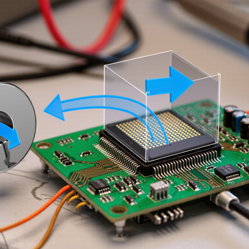
A Hall Magnetic sensor detects magnetic fields through the Hall effect. Inside its semiconductor element, a small electrical current flows across a thin region. When a magnetic field crosses that current, moving charge carriers shift sideways. This creates a measurable voltage across the element. Tiny signal. Built-in electronics may amplify it and provide an analog voltage or a digital switching output.

The exact response depends on the sensor’s design and the field’s direction. A linear sensor can report changing field strength, while a switch may change state near a set threshold. In a simple bench test, moving a magnet toward the sensor can make its output rise, fall, or switch. The magnet’s pole and alignment matter. This is why checking the datasheet and testing the actual mounting position are practical steps, not optional details.

Hall sensors appear in motor speed detection, position sensing, and non-contact current measurement. In current sensing, the device detects the magnetic field around a conductor rather than touching the current directly. That can help simplify mechanical layouts, though accuracy still depends on calibration, temperature, nearby fields, and circuit design. The basic diagram is useful, but it hides real-world complications. A sensor does not identify a magnet’s purpose; it responds to the field reaching its element. Understanding that distinction makes it easier to choose a suitable device and interpret its output reliably.
What Is a Hall Magnetic Sensor and How Does It Work?

What a Hall Magnetic Sensor Is

A Hall magnetic sensor is an electronic component that detects magnetic fields without touching the source. Inside it, a small piece of semiconductor carries an electric current. When a magnetic field crosses that current, moving charges shift sideways. This creates a measurable voltage, known as the Hall voltage. The effect is subtle. The sensor’s circuitry amplifies or processes that signal so another device can read it.

The sensing element is usually enclosed in a compact package, with pins or pads for power and output. Some sensors provide a changing voltage that indicates field strength and direction; others switch their output when a field passes a set threshold. This makes them useful for detecting a magnet near a moving part, such as a wheel or a small sliding panel. They can operate through plastic or other nonmagnetic covers, which helps keep the sensing area sealed. Still, the reading is not magic. Distance, magnet orientation, nearby magnetic materials, and temperature can affect the result. A sensor may seem inconsistent if its placement shifts by only a few millimeters. That detail is easy to overlook during early testing.


The Hall Effect Behind Magnetic Field Detection

A Hall magnetic sensor detects a magnetic field through a small voltage created inside a current-carrying semiconductor. When a magnet approaches, its field pushes moving charges sideways. This separation creates a voltage across the material, at right angles to both the current and the magnetic field. A tiny voltage appears. The sensor’s electronics measure that voltage and convert it into a useful signal, such as a changing output voltage or a simple on-off response.

The effect is easiest to picture with a small sensor beside a rotating wheel. Each passing magnet changes the field at the sensor, producing pulses that can indicate speed or position. Stronger fields generally produce larger Hall voltages, though the relationship depends on the sensor’s design and operating conditions. Temperature, nearby magnetic materials, and electrical noise can all affect the reading. In practice, the signal is not perfectly clean. That small imperfection matters when a system must detect a very weak field or time each pulse accurately. Careful placement, stable power, and basic signal filtering help make measurements more dependable. A Hall sensor does not need physical contact with the moving magnet, which can reduce wear, but the gap still needs attention.

How a Hall Sensor Converts a Field into a Signal

What Is a Hall Magnetic Sensor and How Does It Work?

A Hall sensor turns a magnetic field into an electrical signal through the Hall effect. Current flows through a thin semiconductor plate. When a magnetic field crosses the plate, charge carriers shift sideways, creating a small voltage across its edges. The direction matters: reverse the field, and the voltage polarity reverses.

Small change. Big clue.

The signal chain makes this effect useful. A sensor circuit amplifies the Hall voltage, compensates for temperature drift, and converts the result into an analog output or digital switch. For example, a rotating magnet passing a sensor can create pulses that reveal speed or position. NIST’s Guide to the SI defines one tesla as one weber per square metre, giving engineers a consistent unit for describing that field. IEC 60747-14-5:2010 covers Hall-effect magnetic sensors and their electrical characteristics. In a practical assembly, however, nearby steel, air gaps, and mounting tolerances can distort the field. That offset is easy to underestimate. A sensor may be accurate on a test bench yet read differently once installed beside a motor or bracket. Calibration helps, but it cannot make poor placement disappear.

Key Components and Common Sensor Types

A Hall magnetic sensor combines a semiconductor Hall plate with signal-conditioning circuitry. When magnetic flux crosses the plate, it creates a small voltage across it. An amplifier strengthens that signal, while a comparator or converter helps turn it into a usable output. The package also protects the delicate sensing element. Small parts, precise work.

Common types serve different tasks. A digital switch changes state when a magnetic threshold is reached; unipolar versions respond to one pole, while latching versions switch between opposite poles. Linear Hall sensors provide a changing output, useful for measuring position or current. Three-axis devices detect fields along multiple directions. They can reveal more, but calibration and alignment matter.

The International Energy Agency’s Global EV Outlook 2024 reports nearly 14 million electric cars sold in 2023, about 18% of global car sales. That growth helps explain rising demand for motor-position and current sensing. Yet a Hall sensor is not automatically the right choice: range, temperature drift, air gap, and magnetic interference all affect readings. A sensor may work on the bench, then behave differently inside a warm motor housing. Easy to overlook.

What Is a Hall Magnetic Sensor and How Does It Work?

Key components and common sensor types

How to read the chart: Single-axis switches, latches, and linear sensors measure one field axis; a 3D Hall sensor measures three. A Hall sensor uses a Hall element to detect magnetic fields, while signal-conditioning circuitry and an output stage provide a usable signal. Exact configurations vary by device.

Where Hall Magnetic Sensors Are Used and What Affects Them

Hall magnetic sensors appear in electric motors, wheel-speed systems, lift controls, and factory conveyors. They detect a magnetic field through the Hall effect, then convert it into a voltage or switching signal. In a vehicle, a sensor can track a rotating toothed ring; each passing tooth changes the field and produces pulses for speed measurement. IEA’s Global EV Outlook 2024 reported that electric-car sales were expected to exceed 17 million that year, or more than one in five cars sold. That growth expands the need for reliable motor and position sensing, though the report does not measure Hall-sensor shipments directly.

Performance depends on more than the sensor itself. The air gap between sensor and magnet matters: a few extra millimeters can weaken the signal. Magnet direction, temperature, vibration, and nearby steel can also shift readings or introduce stray fields. Small gaps matter. In current measurement, the conductor’s distance and current level affect the magnetic field being sensed. Engineers typically check the full assembly across operating temperatures and realistic mounting tolerances, not just on a clean bench. A practical snag: tightly packed equipment can make stray-field sources hard to identify. Calibration helps, but it cannot fix poor placement or an unsuitable sensor range.

What Is a Hall Magnetic Sensor and How Does It Work? - Where Hall Magnetic Sensors Are Used and What Affects Them

Topic How It Works or Typical Behavior Common Uses Factors That Affect Performance
Hall effect When current flows through a conductive or semiconductive element, a magnetic field perpendicular to that current creates a transverse voltage called the Hall voltage. In an idealized plate, its magnitude depends on current, magnetic-field strength, carrier density, and plate thickness. Magnetic-field detection, position sensing, speed measurement, and non-contact current measurement. Field strength and direction, element geometry, bias current, material properties, temperature, and electrical noise.
Linear Hall sensor Produces an analog output that changes with the magnetic field over its specified operating range. The output may be centered around a reference voltage when the field is near zero, but the exact transfer function depends on the device. Linear position measurement, joystick sensing, travel or pedal sensing, and magnetic-field measurement. Field range, magnetic alignment, distance from the magnet, offset, sensitivity, temperature drift, and supply or output loading.
Hall switch Changes its output state when the magnetic field crosses a switching threshold. Unipolar switches respond primarily to one magnetic polarity; bipolar switches may require the opposite polarity to release. Proximity detection, lid or cover detection, end-of-travel detection, and simple rotational speed sensing. Operate and release thresholds, field polarity, magnet placement, air gap, stray magnetic fields, and temperature.
Hall latch Typically switches on in response to one magnetic polarity and switches off in response to the opposite polarity. This behavior can provide reliable position or rotation-state detection when a magnet alternates poles. Brushless motor rotor-position sensing, rotational speed detection, and magnetic position encoding. Magnet pole pattern, field strength at the sensor, air gap, sensor orientation, switching thresholds, and nearby magnetic interference.
Multi-axis Hall sensor Measures magnetic-field components along two or three axes, depending on the sensor design. The component readings can help determine field direction as well as strength. Three-dimensional magnetic-field measurement, orientation sensing, and position systems that use multiple field components. Axis alignment, cross-axis sensitivity, calibration, field range, temperature, and the position and orientation of the magnet.
Current sensing A Hall sensor can measure the magnetic field produced by current in a nearby conductor. Because the measurement is magnetic, the sensing element can be electrically isolated from the measured conductor in suitable sensor designs. Current monitoring in power electronics, motor drives, battery systems, and electrical protection circuits. Conductor geometry and position, distance to the sensor, external fields, magnetic-core design where used, temperature, and calibration.
Rotational speed and position A passing magnet or magnetic target changes the field at the sensor. Repeated output transitions can indicate rotation or movement; the relationship between transitions and mechanical position depends on the target pattern and sensor arrangement. Motor commutation, shaft-speed measurement, wheel or gear sensing, and contactless position feedback. Target pole spacing, air gap, rotational speed, sensor placement, field strength, vibration, and the sensor's response time.
Installation and operating conditions Hall sensors do not need physical contact with a magnetic target, but the field at the sensing element must fall within the device's operating range and have the appropriate direction or polarity. Applications in appliances, vehicles, industrial equipment, consumer electronics, and automation systems. Air gap, mechanical tolerances, magnet aging or temperature changes, nearby ferromagnetic materials, stray fields, supply voltage, and electromagnetic interference.