Leave Your Message
Choosing the right Hall Switch Sensor is rarely a matter of selecting the smallest package or the lowest price. The real decision begins with the magnetic environment, switching behavior, and mechanical limits of the application. A door sensor, brushless motor, automotive position detector, and industrial actuator may all use Hall technology. Their requirements are not interchangeable.
Edward Ramsden, author of Hall-Effect Sensors: Theory and Application, offers a useful principle: “The Hall effect provides a direct way to sense magnetic fields without mechanical contact.” That contactless operation can reduce wear, noise, and maintenance. However, it does not remove design risks. A magnet placed two millimeters off-axis may produce a weaker signal than expected. Nearby steel can distort the magnetic path. Temperature can also shift operating points and release thresholds.
This guide examines the practical factors behind a reliable Hall Switch Sensor choice. It considers unipolar, bipolar, and omnipolar behavior, along with digital output compatibility, supply voltage, response speed, hysteresis, and environmental protection. Small details matter. A motor running at 8,000 revolutions per minute needs faster switching than a cabinet-door monitor. A sensor inside an engine compartment needs stronger temperature and vibration tolerance.
There is no perfect selection. That is worth admitting. Early prototypes often expose assumptions that a datasheet cannot reveal. Testing the actual magnet, air gap, housing, and circuit together provides stronger evidence than relying on isolated specifications. The following sections turn those observations into a practical selection process for choosing a Hall Switch Sensor with greater confidence.
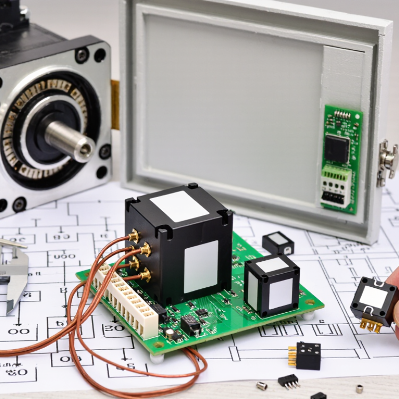
How to Choose a Hall Switch Sensor for Your Application?
Define the Role and Working Principle of a Hall Switch Sensor
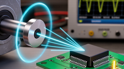
A Hall switch sensor detects magnetic fields and converts them into an electrical switching signal. It uses the Hall effect, where a current-carrying semiconductor responds to a magnetic field. When the field reaches the operating threshold, the output changes state. When the field weakens, the release threshold restores the original state. The difference between these thresholds is called hysteresis. It helps prevent unstable output near the switching point.
In practical equipment, a small magnet can trigger the sensor through a plastic cover. This action can confirm a door position, count rotating parts, or detect a piston stroke. Digital Hall switches usually provide a clear high or low signal. Some use open-drain outputs, while others use push-pull outputs. The controller must match this electrical behavior. A wrong connection may produce unreliable readings.
Selection should begin with the sensor’s role, not its package size. Check supply voltage, output current, switching frequency, operating temperature, magnetic polarity, and recommended air gap. A rotating shaft may need fast switching and careful alignment. A safety cover may need stable operation across vibration and temperature changes. The air gap rarely stays perfect in real machinery. Mounting tolerances, dust, and magnet strength can shift it. A bench test is useful, but it can create false confidence. Test the sensor inside the actual enclosure, under expected temperature and vibration. Datasheet limits should guide the design, while measured results should challenge assumptions.
| Selection Dimension | What to Check | Typical Options or Values | Working Principle and Selection Guidance | Suitable Applications |
|---|---|---|---|---|
| Operating Principle | How the sensor reacts to a magnetic field | Hall-effect switching | A Hall element detects the magnetic field perpendicular to its active surface. Internal signal conditioning changes the small Hall voltage into a digital switching signal when the magnetic field reaches the operate or release threshold. | Position detection, rotation sensing, end-of-travel detection, door and lid monitoring |
| Switching Function | Required magnetic response | Unipolar, omnipolar, or bipolar | Unipolar: responds mainly to one magnetic pole. Omnipolar: can respond to either north or south pole. Bipolar: one pole operates the switch and the opposite pole releases or toggles it. | Unipolar for defined magnet orientation; omnipolar for simple presence detection; bipolar for alternating magnetic fields and rotary applications |
| Output Type | How the sensor interfaces with the control circuit | Open-drain or open-collector digital output | The output transistor normally requires an external pull-up resistor. Verify whether the output is active-low or active-high, the maximum sink current, and compatibility with the controller input voltage. | Microcontrollers, logic inputs, motor controllers, industrial control boards |
| Normally Active State | Output condition without the required magnetic field | Normally high or normally low, depending on device configuration | Choose the logic state that provides a fail-safe interface and minimizes software or circuit inversion. Confirm the state at power-up and during magnetic-field transitions. | Safety interlocks, access monitoring, motor commutation, equipment status feedback |
| Supply Voltage | Available system voltage and allowable operating range | Common ranges include approximately 2.4–5.5 V or 4.5–24 V, depending on the sensor family | The sensor supply range must include the lowest and highest actual system voltages, including tolerance, startup variation, and transient conditions. Check the required decoupling capacitor. | Low-voltage portable electronics, automotive systems, industrial equipment, battery-powered products |
| Magnetic Sensitivity | Magnetic field required to operate and release the switch | Specified by operate point, release point, and hysteresis in gauss or millitesla | 1 mT equals 10 gauss. Higher sensitivity allows detection with a weaker field or greater air gap, but may increase susceptibility to stray magnetic fields. Select using the guaranteed maximum operate threshold and minimum release threshold. | Compact assemblies, sealed enclosures, sliding mechanisms, magnet-based position sensing |
| Magnetic Hysteresis | Difference between operate and release thresholds | Device-specific; commonly several gauss to several tens of gauss | Hysteresis prevents output chatter when the magnet is near the switching point or when vibration causes small field fluctuations. More hysteresis is useful in mechanically unstable environments. | Vibrating equipment, rotating targets, doors, latches, and applications with mechanical tolerance variation |
| Magnet Polarity | Whether the sensor requires a specific magnetic pole | North-pole sensitive, south-pole sensitive, or either-pole sensitive | Magnet orientation must match the sensor’s specified active pole and sensing axis. Either-pole devices simplify assembly, while single-pole devices can provide more controlled switching behavior. | Magnetically actuated switches, cover detection, position encoding, rotary sensing |
| Sensing Distance | Distance between the sensor and magnet at switching | Application-dependent; commonly a few millimetres to several centimetres | Distance depends on magnet strength, magnet size, air gap, alignment, temperature, nearby ferromagnetic materials, and the sensor’s guaranteed thresholds. Design with tolerance margins rather than using the nominal distance alone. | Non-contact limit detection, plastic housings, fluid-level mechanisms, shaft and wheel sensing |
| Target Speed | Maximum frequency of magnetic transitions | From low-speed switching to several kilohertz or higher, depending on the sensor | Check the specified response time, propagation delay, internal filtering, and output rise and fall times. The switching frequency must remain below the sensor’s guaranteed operating limit. | Fan speed measurement, wheel-speed sensing, motor commutation, gear-tooth detection |
| Response Time | Time required for the output to change after the threshold is crossed | Typically microseconds to milliseconds, depending on design and filtering | Fast response is important for high-speed rotation and precise timing. Built-in filtering can improve noise immunity but may reduce response speed. | High-speed motors, encoders, frequency measurement, rapid position monitoring |
| Operating Temperature | Temperature range of the complete sensor and magnetic system | Common ranges include approximately −40 °C to +85 °C or −40 °C to +125 °C | Verify the temperature range of both the Hall switch and the magnet. Magnetic strength and Hall thresholds vary with temperature, so use worst-case specifications when calculating the air gap. | Automotive compartments, outdoor equipment, appliances, industrial machinery |
| Power Consumption | Continuous supply current and standby current | From microampere-level duty-cycled operation to several milliamperes for continuously active devices | Low-power devices extend battery life. For battery applications, compare average current rather than only the active current, and check whether the sensor supports sleep or duty-cycled operation. | Wearables, wireless devices, smart locks, battery-powered sensors, portable instruments |
| Output Drive Capability | Load current, leakage current, and logic-level compatibility | Typically intended for logic inputs; some outputs can sink several milliamperes | Confirm the maximum output voltage, sink current, leakage current, and pull-up resistor range. Do not connect a load that exceeds the output transistor’s rating. | Digital control inputs, indicator circuits, counters, embedded systems |
| Environmental Protection | Resistance to moisture, dust, vibration, and chemicals | Package and assembly dependent; sealed assemblies may achieve IP-rated protection | Hall sensors are non-contact devices, but the package, connector, cable, and magnet assembly still require environmental protection. Select an enclosure and sealing method suitable for the installation location. | Outdoor equipment, pumps, appliances, vehicles, factory automation |
| Package and Mounting | Physical size, sensing orientation, and installation method | Surface-mount, through-hole, leaded, cable-connected, or integrated module | Ensure the active Hall area is correctly aligned with the magnetic field. Consider PCB space, mechanical tolerances, assembly direction, and the distance between the sensor and magnet. | Compact electronics, control panels, rotating assemblies, molded or sealed products |
| Noise Immunity | Resistance to electrical and magnetic interference | Depends on hysteresis, filtering, shielding, layout, and signal conditioning | Use adequate hysteresis, proper grounding, supply bypassing, suitable pull-up resistance, and physical separation from high-current conductors. Evaluate nearby permanent magnets, motors, and solenoids. | Motor drives, power electronics, industrial control systems, electrically noisy equipment |
| Reliability and Service Life | Mechanical wear, switching endurance, and long-term stability | Solid-state switching with no mechanical contacts | Because the Hall switch operates without physical contact, it avoids contact bounce and mechanical contact wear. Reliability still depends on electrical overstress, thermal conditions, vibration, sealing, and correct magnetic design. | Frequent-cycling mechanisms, sealed products, long-life position sensors, automated equipment |
| Recommended Selection Method | Order in which the design should be evaluated | Function → Magnetic design → Electrical interface → Environment → Verification | Define the target position and switching logic first; calculate the magnetic field over the full air-gap tolerance; verify supply and output compatibility; check temperature and environmental limits; then test worst-case magnet, alignment, vibration, and temperature conditions. | All Hall switch sensor applications |