
Hall Effect Sensors turn an invisible magnetic field into a measurable electrical signal. Their operation begins with a simple physical event: moving charge travels through a thin semiconductor while a magnetic field pushes those charges sideways. This produces a small voltage across the device. Edwin Hall, the physicist who discovered the effect in 1879, described the principle in modern terms as follows: “A magnetic field can deflect moving electric charge sideways.” That compact idea still guides today’s sensor design.
In practical equipment, the sensor may sit beside a rotating motor shaft, hidden inside a wheel-speed assembly, or near a current-carrying conductor. A magnet passes nearby, and the sensor responds with an analog voltage or a clean digital pulse. Engineers use these signals to measure position, speed, proximity, and electrical current without physical contact. The result can be precise, fast, and mechanically durable.
Real applications are less perfect. Temperature can shift the output. Stray magnetic fields may create noise. Poor alignment can weaken the signal. A careful engineer checks the datasheet, magnetic polarity, supply voltage, and switching threshold before trusting the reading. An oscilloscope often reveals what a basic meter misses: delayed edges, unstable pulses, or unexpected interference. Hall Effect Sensors are not magic components. They are practical tools that reward correct placement and honest testing. This article explains their structure, working principle, major types, applications, and limitations, while leaving room for one necessary question: does the sensor truly measure the field, or merely respond to a badly controlled setup?
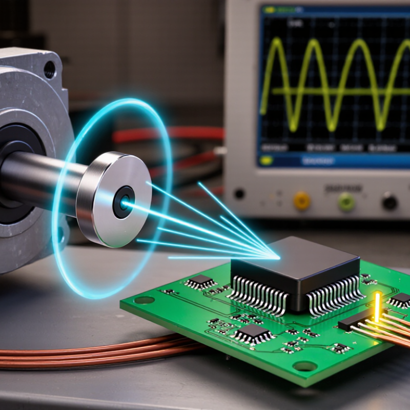
A Hall effect sensor is an electronic device that detects a magnetic field and converts it into an electrical signal. Its name comes from the Hall effect, discovered by Edwin Hall in 1879. When current flows through a thin semiconductor plate, moving charge carriers experience a sideways force inside a magnetic field. This force creates a small voltage across the plate. That voltage is called the Hall voltage. It changes with magnetic field strength and direction.
In a basic circuit, a steady current passes through the sensing element. A magnet, rotating gear, or nearby energized conductor changes the surrounding magnetic field. The sensor measures the resulting Hall voltage and sends an analog or switching output. A digital output changes state at a defined magnetic threshold. An analog output varies continuously, revealing position, speed, or current level. No physical contact is required. That reduces mechanical wear.
Practical accuracy depends on alignment, air gap, temperature, and magnetic material. During a bench check, moving a magnet sideways can produce a weaker signal than expected. This detail is easy to overlook. The simple explanation is useful, but incomplete. Engineers compare readings with a calibrated reference and inspect the supply voltage. Hall sensors are useful, but they are not magically immune to noise. Nearby fields, vibration, and poor grounding can distort measurements. The basic principle remains simple: magnetic influence becomes measurable voltage, then useful information.

A Hall effect sensor detects magnetic fields through a thin conductive or semiconductor element. Its essential parts are a Hall plate, bias-current source, magnetic target, signal amplifier, and output stage. The plate usually sits between two electrical terminals. Current flows across it. When a magnetic field crosses the current path, charged carriers curve sideways. This movement creates a voltage across the other pair of terminals. That voltage is the Hall voltage. The output is small.
Its size depends on current, field strength, carrier properties, and plate geometry. A stronger field usually produces a larger voltage, but only within the sensor’s useful range. Polarity also matters. Reversing the magnetic field reverses the Hall voltage. In practical circuit testing, the amplifier converts this tiny differential signal into a readable analog or switching output. Filtering may reduce vibration and electrical noise, while a stable supply protects measurement accuracy. Noise still wins. A poorly centered magnet can create a misleading result.
Reliable designs keep the sensing gap controlled and align the magnetic field with the plate’s sensitive axis. Temperature changes can alter carrier behavior and offset voltage, so calibration is often necessary. I have found that checking the zero-field output before loading the circuit reveals wiring errors quickly. It is not a substitute for a full test. Mechanical movement, nearby steel, and current-carrying wires can also distort readings. Engineers compare calculated Hall voltage with measured data under several field levels. That comparison can expose assumptions that looked reasonable on paper.
What Are Hall Effect Sensors and How Do They Work?
Step-by-Step Operation of a Hall Effect Sensor
A Hall effect sensor begins with a small semiconductor plate carrying electric current. When a magnetic field crosses the plate, charged particles shift sideways. This movement creates a Hall voltage across the element. The voltage is tiny. An internal amplifier strengthens it for reliable measurement.
The sensor then compares that signal with a reference level. A comparator or Schmitt trigger converts the result into a clean digital output. In a rotating motor, each passing magnet can produce one pulse. A controller counts those pulses and calculates position, speed, or direction. The International Energy Agency’s Electric Motor Systems Annex reports that motor-driven systems consume roughly half of global electricity. Accurate feedback therefore has practical energy value.
Real testing is less tidy. The field moves. Air gaps change. Heat can shift the sensor’s electrical offset, while nearby metal may distort the magnetic path. I normally check the output with an oscilloscope, especially during slow rotation and sudden load changes. That gap matters. Too much distance can weaken the signal; too little can cause mechanical interference. WSTS reported global semiconductor sales of 626.9 billion dollars in 2024, showing the scale of the wider electronics industry, but market size does not guarantee perfect sensing. A sensor may work on the bench and behave differently inside a vibrating machine. That deserves reflection. Calibration, hysteresis, shielding, and temperature testing should match the real installation, not only the datasheet.
| Step | Operating Stage | What Happens | Electrical Signal or Output | Key Technical Details |
|---|---|---|---|---|
| 1 | Power Supply | A regulated supply provides current to the Hall element and powers the sensor’s signal-conditioning circuit. | The sensor establishes a bias current or bias voltage before magnetic-field measurement begins. | The required supply voltage depends on the sensor design. A stable supply helps reduce measurement error and output drift. |
| 2 | Bias Current Through the Hall Element | A controlled current flows through a thin semiconductor material in a defined direction. | With no magnetic field, the Hall voltage is ideally zero, although a small electrical offset may remain. | The Hall element typically has four terminals: two for bias current and two for sensing the transverse Hall voltage. |
| 3 | Magnetic Field Applied | A magnetic field crosses the current path. Moving charge carriers experience the Lorentz force and are deflected toward one side of the material. | Charge accumulation creates a voltage across the sensing terminals, perpendicular to both the current and magnetic-field directions. | The polarity of the Hall voltage changes when the magnetic-field direction is reversed. |
| 4 | Hall Voltage Generation | The generated Hall voltage is related to the magnetic flux density, bias current, carrier properties, and geometry of the Hall element. | The ideal relationship can be represented as: VH = RH × I × B ÷ t | VH is Hall voltage, RH is the Hall coefficient, I is bias current, B is magnetic flux density, and t is material thickness. |
| 5 | Signal Amplification | Because the raw Hall voltage is usually small, an internal amplifier increases the signal to a usable level. | The amplified signal may be analog, digital, or a pulse waveform depending on the sensor architecture. | Amplification improves interface compatibility but can also introduce offset, noise, gain error, and temperature-related variation. |
| 6 | Temperature and Offset Compensation | Internal circuitry may compensate for changes caused by temperature, bias-current variation, and manufacturing mismatch. | The output becomes more stable over the specified operating-temperature range. | Residual offset and sensitivity drift still depend on the sensor construction, magnetic circuit, supply stability, and operating temperature. |
| 7 | Output Conversion | The conditioned signal is converted into an output format suitable for a control system, measurement instrument, or embedded circuit. | An analog output generally changes continuously with field strength. A digital output changes state when a magnetic threshold is reached. | Some sensors provide a ratiometric output, in which the zero-field level and sensitivity scale with the supply voltage. |
| 8 | Magnetic Threshold Detection | In a switch-type Hall sensor, an internal comparator compares the conditioned signal with a programmed magnetic threshold. | The output switches when the field reaches the operating threshold and may return at a different release threshold. | The difference between operating and release thresholds is called hysteresis. Hysteresis helps prevent rapid switching near the transition point. |
| 9 | Digital Pulse Generation | As a rotating magnet, gear tooth, or magnetic target passes the sensor, the magnetic field changes and produces repeated switching events. | The resulting pulse frequency can represent rotational speed, while pulse count can represent position or travel distance. | The measurable speed range depends on magnetic target geometry, air gap, field strength, sensor response time, and signal-conditioning limits. |
| 10 | System-Level Interpretation | A connected controller interprets the analog level, switching state, pulse frequency, or pulse count as a physical measurement. | The final measurement may represent current, position, speed, proximity, rotation, or magnetic-field strength. | The sensor does not require mechanical contact with the moving target, which enables non-contact detection and reduces mechanical wear. |
Measurement note: A Hall effect sensor responds to magnetic flux density at the sensing element. The accuracy of the complete measurement also depends on magnetic-field uniformity, alignment, air gap, temperature, electrical noise, and the selected output interface.
Hall effect sensors detect magnetic fields without physical contact. A current flows through a thin sensing element, while a nearby magnetic field creates a voltage across it. This voltage changes with field strength and polarity. In practical testing, placing a small magnet near the sensor produces a measurable output within milliseconds. The sensing surface must face the correct direction.
The main types differ in how they report magnetic movement. Analog Hall sensors provide a changing voltage, making them useful for measuring position, speed, or current. Their output may drift with temperature, though. Digital Hall sensors act like electronic switches. They produce a clear high or low signal when the magnetic field crosses a set threshold. This suits door detection, motor timing, and wheel rotation. Some digital versions are unipolar, responding to one magnetic pole. Bipolar types switch with one pole and release with the opposite pole. Latching sensors remain in their last state until the reverse pole appears.
Choosing between these types requires more than checking sensitivity. A linear sensor gives richer data, but its signal needs careful calibration. A switch is simpler, yet vibration can cause unwanted transitions near the threshold. In a bench test, adding hysteresis often improves stability. Magnet distance matters too. I once treated it as a minor detail, but a few millimeters changed the switching point noticeably. Temperature, air gaps, mounting material, and magnetic alignment can also alter real-world performance.
Hall effect sensors detect magnetic fields by producing an electrical signal when a magnetic field interacts with current flowing through a semiconductor. The idealized chart below compares the normalized output behavior of common Hall sensor types.
Analog linear sensors provide an output that changes proportionally with magnetic field strength. Unipolar switches respond mainly to one magnetic polarity, bipolar latches switch states using opposite magnetic poles, and omnipolar switches respond to either polarity. Actual switching thresholds and output ranges vary by sensor design.
Hall effect sensors detect magnetic fields and convert them into electrical signals. A current passing through a thin semiconductor creates a voltage when a magnetic field crosses it. The signal can then indicate position, speed, direction, or electrical current. In a motor, a small magnet may pass the sensor thousands of times per minute. That simple event becomes useful control data.
Common applications include brushless motors, vehicle wheel-speed systems, industrial conveyors, battery monitoring, and contactless switches. Current sensors also measure power without inserting a resistor into the main circuit. This reduces heat and supports electrical isolation. A 2024 MarketsandMarkets report estimates that the global Hall-effect current sensor market could grow from about USD 1.9 billion in 2023 to USD 3.1 billion by 2028. Demand is linked to electrification, automation, and energy-management equipment.
The benefits are practical. Hall sensors have no mechanical contacts, so they can operate quietly and withstand repeated switching. They also use little space. Yet they are not perfect. Temperature changes can shift the output, while nearby magnets may cause false readings. Cheap layouts often create avoidable noise. A sensor placed beside a motor may need shielding, calibration, and software filtering. Response speed, magnetic range, and mounting distance must match the application. A 2023 industry analysis from Grand View Research also identifies automotive and industrial automation as major growth areas, although published market estimates differ. That difference deserves attention before investment decisions.