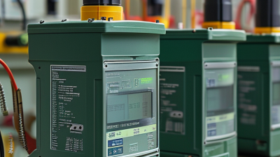
How to Calculate CT Ratio for a Transformer
Choosing a current-transformer ratio is a small calculation with significant consequences for protection and measurement. The ratio compares the rated primary current with the rated secondary current. For a 400/5 CT, the ratio is 80:1: 400 amperes on the primary correspond to 5 amperes on the secondary at rated conditions. In basic terms, divide primary current by secondary current. Simple enough. Small errors matter.
For a transformer, estimate the primary and secondary line currents from its rated power, voltage, and phase arrangement, then select CT ratios that suit the expected currents and connected relays or meters. Three-phase calculations use I = S ÷ (√3 × V), with consistent units. A 1,000 kVA transformer operating at 11 kV draws about 52.5 A on its primary side; the corresponding low-voltage current will be much higher. These figures help frame the choice, but they do not replace a protection study or equipment checks.
IEEE C57.13-2016 and IEC 61869-2:2012 provide authoritative requirements for instrument-transformer ratings, accuracy, and performance. Their guidance matters because ratio alone does not determine whether a CT will serve reliably. Burden, accuracy class, saturation behavior, and the relay’s input rating also matter. Ct On Transformer calculations should therefore be checked against the nameplate, wiring arrangement, and application requirements. Real installations can expose assumptions that look harmless on paper. That is worth remembering. This guide explains the calculation, shows practical examples, and highlights the checks that help prevent a correct-looking ratio from becoming the wrong choice.

Define CT Ratio as Rated Primary Current Divided by Rated Secondary Current
To calculate a current transformer (CT) ratio, divide the rated primary current by the rated secondary current.
The nameplate gives both values. For a CT rated 400/5 A, the ratio is 400 ÷ 5, or 80:1. At its rated primary current, 400 amperes, it delivers 5 amperes on the secondary side. If the primary current is 240 amperes, the ideal secondary current is 3 amperes. Check the plate.
Use the ratio to interpret meter readings: multiply the measured secondary current by 80 to estimate the primary current. A 2.5-ampere reading, for example, represents about 200 amperes on the primary side. This current ratio is not the transformer’s voltage ratio. Also, the ratio alone does not establish measurement accuracy; the CT’s accuracy class and connected burden matter. Verify the rating and wiring against the equipment documentation before relying on readings.
Never leave an energized CT secondary open, since hazardous voltage can develop. If the installation is unfamiliar, have a qualified technician inspect it. Even a correct calculation can mislead when the CT rating or meter setup is wrong.
Check Nameplate Ratings and IEC 61869-2 Secondary Values: 1 A or 5 A
How to Calculate CT Ratio for a Transformer
Read the current transformer’s nameplate before doing the arithmetic. Divide the rated primary current by the rated secondary current. A 400/5 A CT has a ratio of 80:1. At rated primary current, its secondary current is 5 A. Check the full marking, not just the ratio: accuracy class, burden, and polarity also affect whether the CT suits the meter or protection relay. Small details matter.
IEC 61869-2:2012, the international standard for measuring current transformers, identifies 1 A and 5 A as common rated secondary-current values. Choose the value specified by the equipment and project documents; never assume that a replacement CT matches. For equal lead resistance, a 1 A circuit has one twenty-fifth the I²R wiring loss of a 5 A circuit, because losses rise with the square of current. That is useful over long cable runs, but it does not prove the whole measurement system is more accurate. Verify the connected burden and relay input ratings, too. A neat ratio calculation can still hide a mismatch.
How to Calculate CT Ratio for a Transformer
Use the current transformer nameplate ratings: divide the rated primary current by the rated secondary current. For example, a 200/5 A CT has a ratio of 200 ÷ 5 = 40:1. IEC 61869-2 includes 1 A and 5 A as standard rated secondary-current values.
Reading the chart: At rated primary current, each CT is designed to deliver its rated secondary current. Always check the nameplate and applicable installation requirements before selecting or working with a CT.
Calculate a 400 A/5 A CT Ratio: 400 ÷ 5 = 80:1
For a current transformer (CT) marked 400 A/5 A, divide the primary rating by the secondary rating:
400 ÷ 5 = 80.
The ratio is 80:1.
In practical terms, 80 amperes flowing through the primary correspond to about 1 ampere on the secondary.
At 200 A primary current, the expected secondary current is about 2.5 A.
The arithmetic is simple. The setup still deserves a careful check.
Read the CT nameplate and confirm which terminals are designated primary and secondary. Also check the connected meter or relay’s input rating; a 5 A secondary should not be assumed suitable for a 1 A input.
A useful field check is to compare the measured primary current with the secondary reading, allowing for instrument accuracy and operating conditions. Small differences can occur.
One easy detail to overlook is the ratio direction: 80:1 describes primary current relative to secondary current, not the reverse.
Never leave an energized CT secondary open, since hazardous voltage may develop; follow the equipment manufacturer’s instructions and have qualified personnel perform testing.
Convert Secondary Current to Primary Current Using the 80:1 Ratio
For a current transformer marked 80:1, the primary current is 80 times the secondary current. The ratio means 80 amperes on the primary side correspond to 1 ampere on the secondary. If a meter reads 3.2 A, calculate:
3.2 × 80 = 256 A
The estimated primary current is 256 A. Simple enough.
Check the CT nameplate and meter settings before using the result. Some meters apply the ratio automatically, so multiplying again would inflate the reading. Confirm whether the displayed value is secondary current or scaled primary current. That distinction is easy to miss. Also, an 80:1 ratio describes current conversion; it does not mean the transformer always carries 80 A. Actual readings change with the connected load. The calculation is useful, but it cannot replace checking the instrument setup and wiring.
Tips: Write down the units beside each number: 3.2 A × 80 = 256 A. Compare the calculated value with the equipment’s expected load. If the CT is energized, never leave its secondary circuit open; follow qualified site procedures before handling connections. Recheck the label, too—ratio markings and meter configurations can be confusing.
Verify Ratio, Polarity, and Accuracy Class Against the CT Nameplate
How to Calculate CT Ratio for a Transformer
A current transformer’s ratio compares its rated primary current with its rated secondary current. A nameplate marked 600:5 represents 120:1, so 600 amperes on the primary corresponds to 5 amperes on the secondary under rated conditions. Check both numbers on the actual nameplate before using this calculation; do not infer the ratio from the transformer’s size or appearance. Small details matter.
Then verify polarity and accuracy class. Find the P1/P2 primary and S1/S2 secondary markings, and compare them with the wiring diagram and intended current direction. Reversed polarity can produce misleading meter readings or affect protective equipment operation. The accuracy class describes performance within specified operating conditions; it is not a substitute for the ratio. Check the stated burden, often shown in VA, and confirm the CT’s metering or protection designation suits the connected device. A mismatch may affect accuracy. Field checks can also reveal wiring or loading issues, but readings alone do not prove the nameplate specifications. I would pause and recheck if labels are damaged or results seem inconsistent. Never leave an energized CT secondary open; follow site procedures and qualified testing practices.
How to Calculate CT Ratio for a Transformer - Verify Ratio, Polarity, and Accuracy Class Against the CT Nameplate
Calculation: CT ratio = rated primary current ÷ rated secondary current. Expected secondary current = test primary current ÷ CT ratio. Spot-check deviation = (measured secondary current − expected secondary current) ÷ expected secondary current × 100%. A spot check does not by itself verify the nameplate accuracy class; accuracy depends on the specified standard, burden, and test conditions. Never leave a CT secondary circuit open while primary current is flowing.