Choosing a Choke Core in 2026 starts with the job it must do, not a material name on a supplier page. A core used for common-mode noise suppression faces different demands from one carrying substantial power current. Get that distinction wrong, and an otherwise attractive part may run hot or provide little useful impedance.
Start with the operating frequency, current, voltage, and available space. Then compare core material, dimensions, winding turns, impedance curves, and saturation behavior against the manufacturer’s datasheet. Ferrite grades vary: performance at one frequency does not guarantee performance across the full range. Check winding resistance and temperature limits, too. Small details matter.
For an EMI choke, look for impedance near the frequencies causing trouble, then verify results in the actual circuit. For a power choke, examine inductance under DC bias and expected peak current. A tidy datasheet is useful, but measurements can expose gaps between a specification and real operating conditions. That part is easy to overlook.
There is no single best core. It depends. A practical selection balances electrical performance, size, heat, cost, and availability, while leaving room for manufacturing variation. Even experienced engineers may need to revise a choice after testing; that is not failure, just evidence. In this guide, we’ll explain how to compare choke-core options in 2026 and identify the questions worth asking before committing to a design.
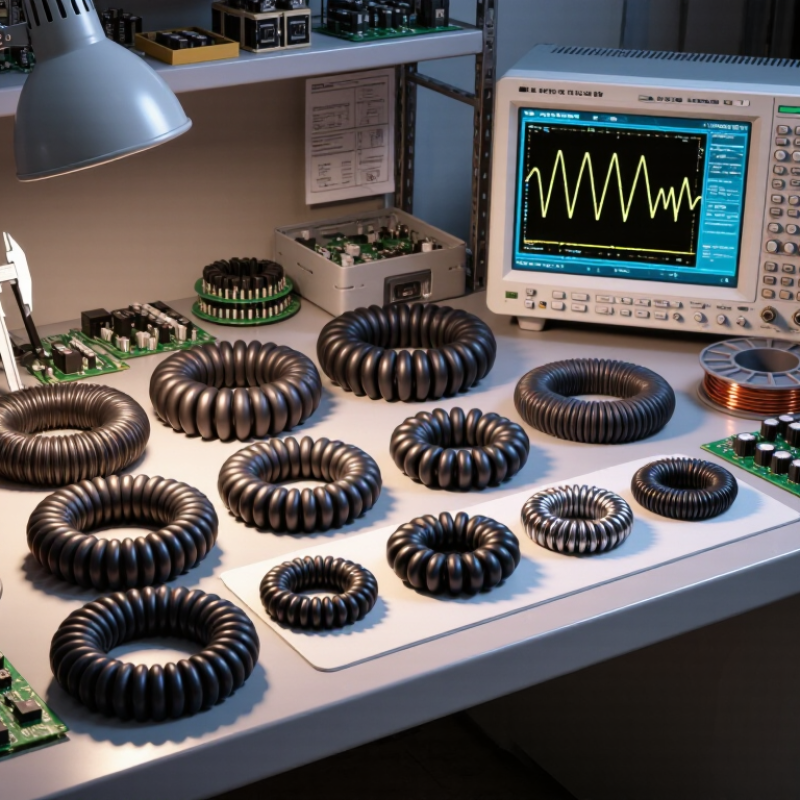
A choke core is the magnetic path inside an inductor or common-mode choke. It helps resist unwanted high-frequency current while allowing the intended current to pass. In a common-mode choke, two windings share a core: normal currents largely cancel their magnetic fields, while noise currents reinforce them. The core is not a noise cure by itself. Layout and winding design matter too.
You’ll find chokes in power supplies, motor drives, inverters, and signal cables. These devices can produce switching noise that travels through wires or radiates nearby. The IEA’s 2011 report, Energy-Efficiency Policy Opportunities for Electric Motor-Driven Systems, estimated that motor-driven systems use about 45% of global electricity. That scale helps explain why noise control in drives matters. Small component. Wide reach.
When choosing a core, match its material and size to the frequency range, current, and heat conditions. Ferrite is common for high-frequency suppression; other magnetic materials may suit different frequency or energy needs. Check impedance curves, saturation limits, and temperature ratings—not just the core’s shape. A compact core may fit neatly, yet lose effectiveness at the frequencies that matter. Easy to overlook. Real measurements can still disagree with a tidy datasheet prediction, so test the finished assembly under operating conditions.
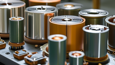
Before selecting a choke core, define its electrical job in the actual circuit. Record the operating frequency, required inductance, ripple current, and maximum continuous current. Check inductance under DC bias, not only the value measured at zero current. Saturation can reduce performance quickly. Compare core-material loss data across the full frequency and temperature range. A core that works well at room temperature may run hot inside a sealed enclosure. Also specify allowable impedance, voltage, and temperature rise. Leave margin for component tolerances and changing loads.
Mechanical limits deserve equal attention. Set the maximum core dimensions, winding window, mounting method, and clearance for leads and insulation. Check whether the winding can be assembled consistently, especially when wire thickness or turn count is high. Small details matter. Consider vibration, nearby heat sources, airflow, and access for inspection. Then review the core’s data against the intended assembly, rather than treating catalogue values as guaranteed results. Prototype testing can expose an awkward fit or unexpected heating. Early calculations are useful, but they are not always right; revise them when measurements disagree.
Choosing a choke core starts with the noise you need to control, not with a familiar shape. Ferrite is often suitable for high-frequency interference because its electrical resistance helps limit core losses. Powdered iron can handle energy storage and DC bias in some power designs, though its losses may rise at higher frequencies. Nanocrystalline materials offer high permeability across useful frequency ranges, but cost, size, and operating conditions still matter. Check the material’s impedance or loss data at your actual frequency. That matters.
Shape affects winding, leakage, and assembly. A toroidal core can confine magnetic flux well, making it useful where low radiated noise is important. An E-shaped core is easier to wind and can accommodate a deliberate air gap for energy storage. Compact drum cores suit space-limited layouts, but their exposed fields may couple into nearby circuits. Fit is not everything. Leave room for insulation, wire bends, and heat to escape.
Match the core to the measured problem: common-mode or differential-mode noise, operating current, frequency range, and temperature rise. Compare impedance curves, saturation limits, and loss figures from reliable datasheets, then test the assembled choke in its intended circuit. A part that looks right on paper can behave differently once winding capacitance and nearby metal enter the picture. I would treat the first choice as a reasoned starting point, not a guarantee.
How to Choose a Choke Core in 2026?
How to Compare Ratings, Losses, and Operating Limits
A choke’s current rating is not a universal pass mark. Check whether it means RMS heating current, saturation current, or a specified inductance drop. Compare values at the same temperature and test frequency. A 10 A rating measured at a 20% inductance decrease may not suit a design that allows only 10%. Check the fine print.
Compare losses at your actual frequency, ripple, and temperature. Core-loss figures from different reports are useful only when their test conditions match. IEC 60205 provides a standardized approach to calculating effective magnetic-core parameters; pair that framework with measured component data. For example, if two candidates dissipate 2.4 W and 1.6 W under identical test conditions, the lower-loss core saves 0.8 W. That difference can still disappear if winding loss or nearby heat dominates.
Check the operating limits together, not one at a time. Core saturation, winding temperature, insulation class, and ambient temperature all shape the safe operating window. A lab value at 25°C may be misleading inside a warm, sealed enclosure. Look for loss curves across frequency and flux density, plus temperature-dependent inductance data. I would also leave margin for tolerances and airflow changes. The awkward part: real assemblies rarely match the tidy test setup.
For a 2026 design, verify a choke core under the conditions it will actually face. Start with the required inductance and operating frequency, then check the manufacturer’s impedance or inductance curve across the full frequency range. A single value at 100 kHz may hide a sharp drop near your switching frequency. Check tolerance, rated current, and the core material’s stated temperature limits, too.
Measure the assembled choke, not only a loose sample. Use a suitable impedance analyzer or network analyzer, with a fixture that minimizes lead effects. Record inductance, impedance, and winding resistance at room temperature. Then apply the expected DC bias and operating current. Watch for inductance loss, unexpected heating, or noise. Small differences matter.
Test again on the actual board. Nearby copper, spacing, and parasitic capacitance can change high-frequency behavior. Run the design at its highest expected ambient temperature and inspect the core after thermal stabilization. Compare results with the datasheet, but leave margin for production variation. A clean bench plot is reassuring, not conclusive. Sometimes the first fixture needs improvement; that is easy to overlook. Keep the setup, instrument settings, and measured results with the design record so another engineer can repeat the check.
| Design Check | Data to Record | How to Verify | Decision Criterion |
|---|---|---|---|
| Operating conditions | Switching frequency, current waveform, peak and RMS current, ambient temperature, and cooling conditions. | Use the actual converter or filter operating profile. Include startup, overload, and other relevant transient conditions. | Evaluate the core and finished choke against the full operating range, not only nominal current or frequency. |
| Core material and construction | Material type, core geometry, effective area, effective magnetic path length, and whether the core has a gap or distributed-gap structure. | Confirm material and geometry data from the component or material specification. Compare ferrite, powdered magnetic material, or other candidates using loss, bias, and temperature data for the intended operating conditions. | Select based on measured or specified performance at the design frequency, flux swing, temperature, and DC bias. Material names alone do not establish suitability. |
| Inductance at operating frequency | Inductance, measurement frequency, test signal level, temperature, and instrument method. | Measure the assembled choke with an LCR meter or impedance analyzer using documented test conditions. | Inductance must meet the design’s minimum and maximum limits under the stated measurement conditions. |
| Inductance under DC bias | Inductance versus DC current, including the maximum continuous current and relevant transient current. | Use a bias fixture or current-injection test setup. Record inductance at multiple current points and at the specified temperature. | At the required operating current, inductance must remain above the minimum needed for ripple, filtering, or energy-storage requirements. |
| Flux-density calculation — illustrative example | Example assumptions: winding voltage = 12 V, applied interval = 4 µs, turns = 20, effective core area = 25 mm². | For a rectangular voltage interval, calculate flux change using ΔB = V × t ÷ (N × Ae). Here, ΔB = 12 × 4 µs ÷ (20 × 25 mm²) = 0.096 T. | This is an example flux swing, not a universal limit. Calculate the actual waveform and confirm peak flux remains within the selected material’s limits over temperature and bias. |
| Saturation and peak current | Peak current, current ripple, turns, effective core area, and the material’s flux-density limits over temperature. | Calculate the flux excursion from the applied volt-seconds and verify it against the material data. Confirm with a current-bias test where practical. | Allow margin for temperature, manufacturing variation, and transients. Do not use a room-temperature saturation figure as the sole pass criterion. |
| Core loss and temperature rise | Frequency, flux swing, waveform, core volume, ambient temperature, and measured winding and core temperatures. | Estimate loss using data applicable to the material and waveform, then test the finished choke at representative load and cooling conditions. | Temperature rise and total loss must stay within the design’s thermal limits. Sinusoidal loss data may not directly predict loss under a non-sinusoidal waveform. |
| Winding resistance and copper loss | DC resistance, RMS current, conductor details, and operating temperature. | Measure winding resistance with a four-wire method where low resistance makes lead errors significant. Estimate DC copper loss with P = IRMS2 × R. | Check resistance and copper loss at operating temperature; include AC winding effects when frequency and construction make them material to the design. |
| Impedance or common-mode performance | Impedance versus frequency, winding configuration, and the frequency range of the unwanted signal. | Measure with an impedance analyzer or network analyzer using the intended winding arrangement and appropriate fixture de-embedding. | Verify impedance in the frequency band that matters. A nominal inductance value alone does not confirm broadband filtering performance. |
| Mechanical and production checks | Core dimensions, gap or mating surfaces, winding clearance, mounting details, and sample-to-sample inductance variation. | Inspect dimensions and assembly, then test representative samples using the same electrical test conditions planned for production. | Confirm mechanical fit and define documented incoming or production limits for the parameters that control performance. |
Note: Limits depend on the converter topology, waveform, material, geometry, and thermal design. Record test frequency, signal level, DC bias, and temperature whenever comparing measurements.