How to Choose the Right Choke Core for Global Sourcing?
Choosing the right Choke Core for global sourcing requires more than comparing prices and catalog dimensions. It demands a clear understanding of electrical performance, operating conditions, supplier capability, and long-term reliability. A choke core influences impedance, noise suppression, heat behavior, and the stability of the finished product. Small material differences can become serious problems during mass production.
Experienced sourcing teams usually begin with the application. They review current range, frequency, voltage, temperature, insulation requirements, and available installation space. Ferrite, iron powder, nanocrystalline, and other core materials offer different advantages. A compact ferrite core may suit high-frequency filtering, while a nanocrystalline core may provide stronger performance in demanding power applications. The correct choice depends on measured data, not attractive marketing language.
Supplier verification matters just as much. Request material specifications, dimensional drawings, test reports, sample records, and traceability documents. Confirm whether the factory controls winding quality, tolerance, packaging, and final inspection. A supplier’s attractive sample may not represent its monthly production capability. That risk is easy to underestimate.
Cost is important, but the cheapest Choke Core can create hidden expenses through overheating, inconsistent inductance, or field failures. Testing prototypes across temperature and load conditions can expose weaknesses early. Even then, results may not predict every real-world situation. Global sourcing involves uncertainty, including transport delays and regional quality differences. Careful documentation, independent testing, and regular communication reduce those risks. The best decision balances performance, compliance, supply continuity, and practical production experience. Some compromises are unavoidable. They should be understood, recorded, and reviewed before approval.
Classify Choke Cores by Material, Shape, and IEC 62024 Requirements
How to Choose the Right Choke Core for Global Sourcing?
Material, shape, and IEC 62024 compliance should guide every choke core decision. Ferrite cores suit high-frequency noise suppression and offer low eddy-current loss. Mn-Zn ferrite generally supports lower frequencies than Ni-Zn ferrite. Powdered iron handles higher DC bias but may generate more heat. Nanocrystalline materials deliver strong permeability in compact common-mode designs. That advantage can raise sourcing costs.
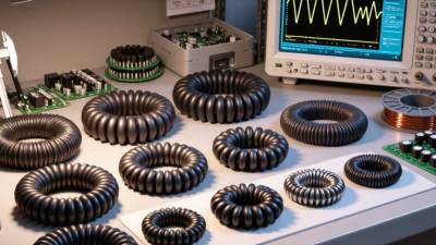
Shape changes both performance and assembly. Toroidal cores provide a closed magnetic path and low leakage. E-cores simplify winding and automated production. Drum cores fit compact differential-mode filters, but their air gaps need careful control.
Select the core after checking inductance, impedance, rated current, temperature rise, and saturation behavior. IEC 62024-1 provides measurement methods for high-frequency inductive components, including electrical characteristics and test conditions. A supplier’s datasheet should show frequency, test voltage, temperature, and fixture details. Otherwise, comparison becomes unreliable.
MarketsandMarkets valued the global EMI shielding market at about USD 7.9 billion in 2024, with continued growth forecast through 2029. This signals strong demand for reliable noise-control components. However, market growth does not guarantee core suitability. I still verify material curves independently. A cheaper core can fail quietly.
Match MnZn Ferrite for 10 kHz–1 MHz and NiZn for 1–100 MHz
How to Choose the Right Choke Core for Global Sourcing?
Start with the operating frequency
When selecting a choke core, begin with the real operating frequency, not only the circuit label. In practical sourcing, MnZn ferrite usually suits applications from 10 kHz to 1 MHz. Its high permeability supports effective impedance at lower frequencies. It can also provide strong common-mode filtering in compact assemblies. At 10 kHz, however, core loss and temperature rise still require careful measurement. Check the material’s impedance, saturation behavior, and loss curves.
Compare materials at higher frequencies
For higher-frequency designs, NiZn ferrite commonly performs better from 1 MHz to 100 MHz. Its higher resistivity helps reduce unwanted eddy-current losses. NiZn is often useful for suppressing fast noise on power, signal, and communication lines. Still, frequency alone does not determine the best choice. Core shape, winding length, cable position, and operating current can change the result significantly. Boundaries can overlap.
Verify the complete assembly
Global sourcing adds another practical concern. Different suppliers may use similar material codes with different test conditions. Request curves measured at your target frequency, temperature, and current. Confirm dimensions, tolerance, surface finish, and safety documentation before approval. A small sample run is wiser than trusting a catalog table. Test the assembled choke, not just the bare core. We once treated 1 MHz as a clean dividing line; the prototype showed otherwise. The best decision came after checking insertion loss and temperature rise across the complete operating range.
Calculate Inductance, Saturation Current, and 20–30% Thermal Headroom
Choosing a choke core starts with the circuit, not the catalog. Define the required inductance, peak current, switching frequency, and ambient temperature. For a gapped core, estimate turns with L = AL × N², then check the result against the core’s usable flux range. Saturation current depends on core area, turns, inductance, and material limits; a first estimate is Isat = Bsat × N × Ae ÷ L. Treat it as an estimate, not a guarantee. Manufacturer test conditions matter.
Thermal margin needs equal attention. Calculate copper and core losses at the actual waveform and frequency, then keep predicted temperature rise about 20–30% below the design limit. That headroom helps cover warmer enclosures, winding variation, and airflow changes.
Small details add up. A few extra turns may improve saturation margin, but they can also raise winding resistance and consume space. Check both effects.
For global sourcing, request the AL tolerance, material data, core dimensions, loss curves, and test conditions. Compare samples under the same current and temperature setup. Catalog figures can look reassuring; a bench test may tell a less convenient story.
Validate EMI Performance Against CISPR 32 and IEC 61000-4-6
How to Choose the Right Choke Core for Global Sourcing?
Validate EMI Performance Against CISPR 32 and IEC 61000-4-6
A choke core should be selected against the equipment’s real EMI risks, not just its material name or impedance rating. CISPR 32 evaluates emissions from multimedia equipment, while IEC 61000-4-6 tests immunity to conducted radio-frequency disturbances. These are different checks. A core that reduces noise during one test may not improve performance in the other.
Ask suppliers for frequency-dependent impedance data, current ratings, and test reports tied to a clearly described setup. Compare results using your cable length, enclosure, grounding, and operating load. For emissions, look for conducted-noise measurements across the relevant frequency range. For immunity, check whether the assembly maintains normal operation during RF injection. Small details matter. A test on a loose core may not represent a tightly assembled product.
Tips: Request raw plots, not only pass statements. Confirm test conditions and sample configuration. Check whether the core’s impedance changes under operating current, and verify that temperature rise stays acceptable.
Global sourcing adds variation in materials, dimensions, and production batches. Set measurable acceptance limits and verify incoming samples before committing to volume. A neat datasheet can still leave gaps; I would treat it as a starting point, not proof of final-system compliance.
Compare Suppliers by AEC-Q200, RoHS, MOQ, Lead Time, and Cost
Choosing a choke core for global sourcing means comparing more than a datasheet price. Check whether the exact part has AEC-Q200 qualification, and request the test scope and supporting records. Qualification can help assess reliability, but it does not guarantee performance in every circuit. Confirm the impedance, rated current, temperature range, and dimensions against your design. Paperwork is not performance.
RoHS documentation should identify the part and match the current product revision. Ask suppliers to clarify MOQ, sample availability, and whether pricing changes at different order volumes. A low MOQ may help with a pilot run, while a higher threshold can lower unit cost but tie up cash. Check whether quoted lead time applies to stocked goods or new production. Get dates in writing. I’ve seen lead-time comparisons become misleading when one quote starts after order confirmation and another starts after payment.
Compare total landed cost, not just unit price. Include tooling or setup charges, packaging, freight, and any inspection costs. Request traceability details and a process for notifying customers about product changes. Then test samples under realistic operating conditions, especially at temperature and current extremes. This takes time. Supplier responses can reveal a lot, though polished documents alone are not enough. Record assumptions in your comparison sheet, and revisit them when order size or delivery location changes.
How to Choose the Right Choke Core for Global Sourcing
How to use this chart: These suggested evaluation weights are a planning template, not supplier or market data. Compare AEC-Q200 qualification evidence and RoHS documentation, then verify MOQ, lead time, and cost against current written quotes for the exact part and order quantity.