What is a Ct Transformer and How Does it Work?
In the world of electrical engineering, understanding a Ct Transformer is essential. This device plays a vital role in measuring current. It allows professionals to monitor and manage electrical systems safely. The Ct Transformer reduces high currents to measurable, safer levels. This function is critical for efficient energy distribution.
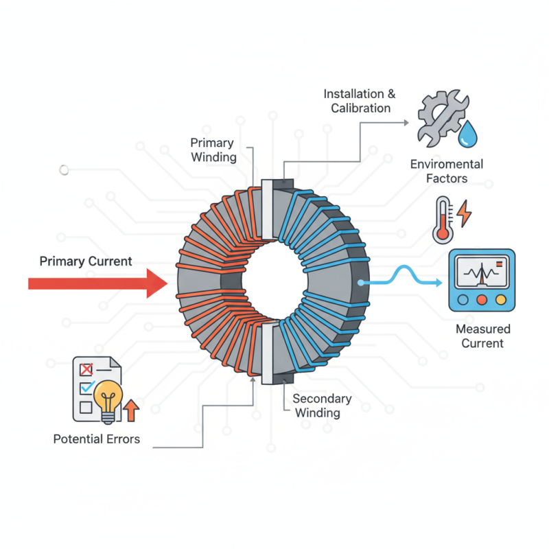
Exploring how a Ct Transformer works reveals its intricate design. It consists of a primary winding and a secondary winding. The primary winding carries the high current while the secondary produces a smaller, proportional current. This flow allows for accurate readings on meters. However, not all systems utilize it effectively. Some installations overlook crucial factors like alignment and calibration.
Diving deeper into its operation, one must consider its limitations. A Ct Transformer can introduce errors if not installed correctly. Additionally, environmental conditions may affect its performance. These flaws remind engineers to continuously assess their systems. Despite its importance, many still struggle with proper implementation. Understanding the Ct Transformer offers a pathway to improved energy management, but it requires attention to detail.
What is a Current Transformer (CT)?
A Current Transformer (CT) is a type of transformer designed to measure alternating current (AC). It allows for safe monitoring of high currents without directly touching the conductor. CTs work by producing a secondary current that is proportional to the primary current flowing through it. This process is vital in protecting electrical circuits.
CT transformers feature a core and winding system. The primary winding usually consists of a single conductor, while the secondary winding has several turns. The magnetic field generated by the primary current induces a current in the secondary winding. This current is typically much smaller and can be easily measured.
In practical applications, CTs help in protecting equipment and monitoring energy usage. However, if improperly calibrated, they can lead to inaccurate readings. Users need to ensure proper installation and regular testing for reliable performance. Sometimes, people overlook these aspects. This can cause significant consequences in energy management. Understanding the operation of CTs is crucial for anyone working with electrical systems.
Principle of Operation for Current Transformers
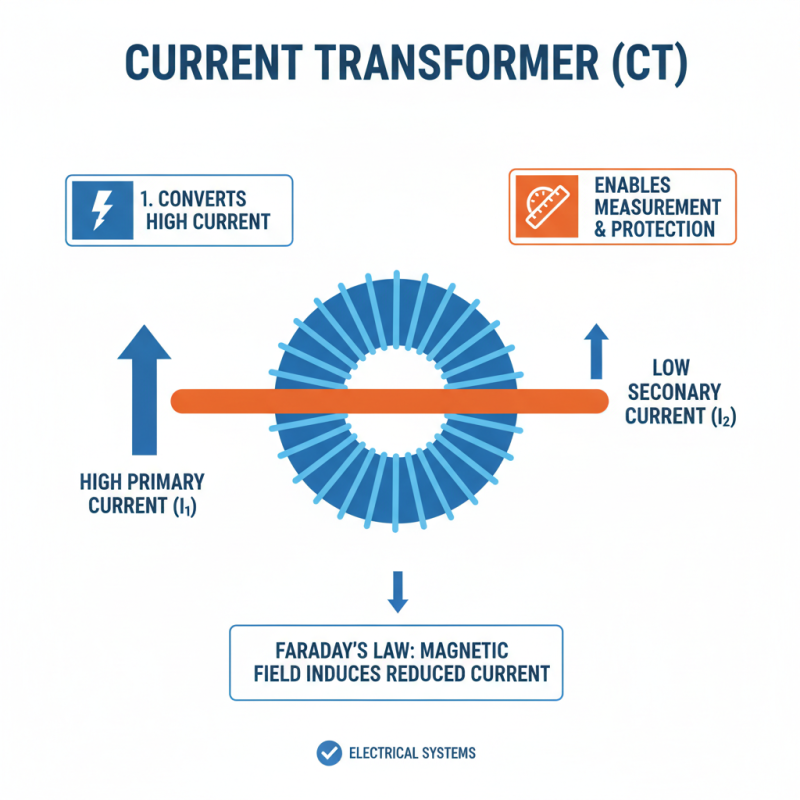
Current transformers, or Ct transformers, are crucial devices in electrical systems. They convert high primary currents into manageable secondary levels. This operation is vital for protection and measurement purposes. The primary current flows through a coil, generating a magnetic field. This field induces a reduced current in the secondary winding, following Faraday's law of electromagnetic induction.
The principle of operation hinges on ratio transformation. A primary winding with fewer turns generates a percentage of the actual current. For instance, a transformer with a 100:5 ratio means that 100 amps in the primary will result in 5 amps in the secondary. This relationship makes monitoring and controlling power easier. However, understanding the exact ratio is critical. Miscalculations can lead to inaccurate readings.
Installation requires careful consideration. If not positioned correctly, a current transformer can produce distortions. Environmental factors, like temperature and humidity, also affect its performance. Regular checks may be necessary to maintain accuracy. It's essential to reflect on these aspects during setup and operation. Users must not overlook these subtleties to avoid operational flaws. Proper usage ensures safety and reliability in electrical management.
Types of Current Transformers and Their Applications
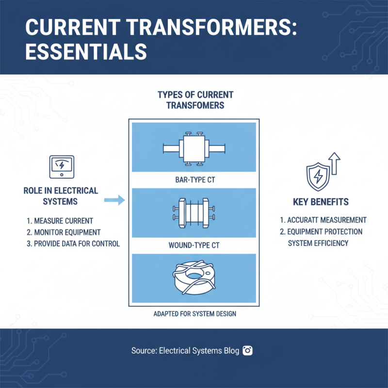
Current transformers (CTs) play a vital role in electrical systems. They measure the current flowing through conductors, providing crucial data for monitoring and controlling equipment. There are several types of current transformers, each with unique applications. These include bar-type, wound-type, and toroidal transformers. Each type serves different needs based on the system's design.
Bar-type transformers are mounted on the bus bar. They are used in medium- to high-voltage applications. Wound-type transformers are versatile and often found in lower voltage systems. They can handle a wide range of currents. Toroidal CTs are compact and suitable for measurement in tight spaces. Their design minimizes electromagnetic interference.
According to industry reports, the global demand for current transformers is projected to grow steadily. A study predicts an annual growth rate of 6.5% through the next five years. This growth reflects the increasing need for efficient monitoring and energy management. As industries evolve, so do their requirements. Current transformer technology must adapt to these changes. There’s a need for innovation and improved accuracy in measurements. Ensuring reliability while reducing costs remains a challenge.
Installation Considerations for CT Transformers
When installing CT transformers, several factors must be considered. Proper placement is crucial to ensure accurate measurements. For instance, the location should minimize electromagnetic interference. This is especially important because interference can lead to erroneous readings. The National Electrical Code provides guidelines on distances from high-voltage equipment. Adhering to these limits ensures safety and performance.
Another aspect to think about is environmental conditions. CT transformers should be installed in areas with appropriate temperature and humidity levels. Excess heat or moisture can degrade performance. According to industry reports, temperature fluctuations can alter the transformer’s accuracy by up to 10%. Therefore, a controlled environment is essential for longevity and reliability.
Accessibility also plays a vital role. Installations need to allow for easy maintenance. A survey stated that 40% of prevention issues arise from inaccessible installations. Proper planning can save time and money in the long run. All these considerations highlight the complexities of installing CT transformers. Neglecting any of these can lead to significant performance issues.
What is a Ct Transformer and How Does it Work? - Installation Considerations for CT Transformers
| Parameter |
Value |
Description |
| Primary Current Rating |
1000 A |
The maximum current the CT is rated to measure. |
| Burden |
5 VA |
The load on the secondary side of the CT. |
| Accuracy Class |
0.5 |
Indicates the accuracy level of the CT under specified conditions. |
| Insulation Level |
Class 1 kV |
The voltage rating for insulation to withstand electrical stress. |
| Operating Temperature |
-20°C to +55°C |
The range of temperatures suitable for operation. |
| Mounting Type |
Panel Mount |
Type of mounting used for installation. |
Safety and Maintenance of Current Transformers
Current transformers (CTs) play a crucial role in monitoring electrical systems. However, their safety and maintenance are often overlooked. Regular inspections help identify issues before they escalate. Dark spots on insulation or excessive heat may indicate potential failures. Proper grounding is essential, as it reduces risks of electric shock.
Maintenance can be straightforward but requires diligence. Cleaning the exterior helps prevent dust accumulation. Checking connections ensures that the CT operates efficiently. Occasionally, internal components might need a closer look. Even minor issues can lead to significant problems if ignored. Always consult the manufacturer's guidelines for specific maintenance practices.
Operators should be aware of safety protocols when working with CTs. Use insulated tools while performing any maintenance. Never work on a live system. Awareness of personal safety is paramount, yet it can sometimes be taken for granted. Each maintenance visit is an opportunity to reflect on safety practices. Small lapses can lead to accidents, so vigilance is essential.
Current Transformer Operational Data
This chart illustrates key specifications of a typical current transformer including rated current, primary voltage, burden, accuracy class, and insulation level. These parameters are essential for understanding the performance and application of current transformers in electrical systems.