How to Calculate Ct On Transformer for Optimal Performance?
Understanding how to calculate Ct on transformer is essential for optimal performance. Proper calculation can enhance efficiency and reduce energy losses. The transformer’s current transformer (Ct) plays a vital role in ensuring accurate measurements and protection.
When calculating Ct on transformer, consider the load and system parameters. These factors influence the selection of the right Ct ratio. An incorrect ratio may lead to inaccurate readings or system failures. Simplicity in calculations is critical, yet challenging.
Many engineers overlook practical field tests. Relying solely on theoretical calculations can be misleading. Real-world conditions may differ significantly. Observations from past implementations often reveal unexpected results. Hence, a blend of theory and hands-on experience proves invaluable for reliable outcomes.
Understanding the Role of Ct in Transformer Performance
Current transformers (CTs) play a crucial role in ensuring optimal transformer performance. They provide accurate current measurements during operation. These measurements are vital for monitoring and protecting electrical systems. Without a properly functioning CT, performance could drop significantly.
Calculating the CT ratio is essential. It helps match the CT with the transformer’s specifications. A mismatch can lead to inaccurate readings. Overloading the CT could also cause damage. Moreover, using the correct ratio enhances system efficiency. Operators often overlook this, but it's key to performance.
Understanding the burden on a CT is as important as calculating the ratio. If the load is too high, errors in measurement occur. Undersized CTs cannot handle the current, leading to saturation. Saturation distorts data, making it unreliable. Therefore, periodic evaluation of the CT is necessary. It ensures that the CT contributes effectively to overall performance. A thorough approach may reveal overlooked details, enhancing overall system reliability.
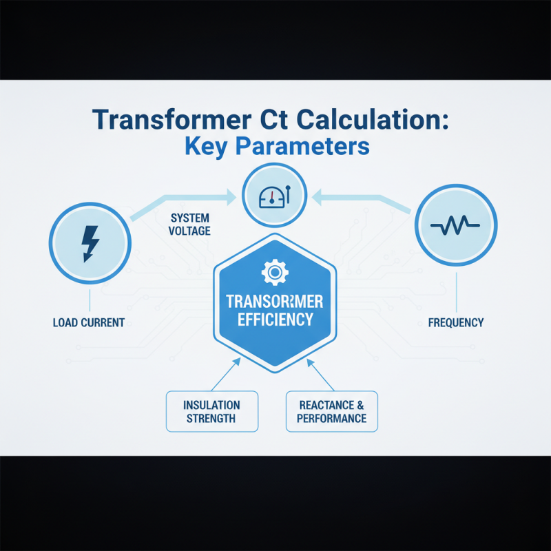
Identifying Key Parameters for Ct Calculation
When calculating the Ct for transformers, certain key parameters play a critical role. Understanding these factors is essential for achieving optimal performance. The primary parameters include load current, system voltage, and frequency. Each element greatly affects the transformer's efficiency. Load current determines the current transformation ratio, while voltage impacts insulation strength. Additionally, frequency influences reactance and overall performance characteristics.
To refine the Ct calculation, one must consider the core material and size. Using high-quality materials can improve efficiency and reduce losses. A larger core can also contribute to better magnetic performance. However, the trade-offs regarding weight and cost should be addressed. It’s important to reflect on the balance between performance and practicality.
Finally, thorough testing and adjustments may be necessary. Once calculations are complete, conducting real-world tests helps validate the theoretical models. Discrepancies often arise, revealing areas for improvement. This iterative process fosters innovation and leads to better transformer design, ultimately enhancing reliability and service life in various applications.
Step-by-Step Guide to Calculate Ct Values
Calculating the correct current transformer (CT) values is essential for optimal transformer performance. This step-by-step guide outlines a practical approach to determining accurate CT ratios.
Begin by gathering essential data about your transformer. Look for the primary current rating and the load conditions. This information will serve as your starting point. You will then utilize the formula: CT ratio = primary current / secondary current. Typically, the secondary current is 1A or 5A. Ensure you verify the load requirements carefully. A common mistake is overlooking these specifications.
Next, consider the burden on the CT. Calculate the total load connected to the secondary side. This calculation impacts the CT's accuracy in measurement. For precise results, it's crucial not to exceed the CT's rated burden. Inadequate or excessive burden can lead to miscalculations. Often, engineers may skip this step or misestimate the burden. This can lead to performance inefficiencies. Adjust the CT values accordingly and recheck your calculations as necessary. The path to optimal performance may require iterations and critical assessments.
Evaluating Impact of Ct on Transformer Efficiency
When evaluating the impact of current transformers (CTs) on transformer efficiency, it's essential to understand their role. CTs measure current, providing input for protective relays and monitoring devices. An optimal CT selection is crucial. Mismatched CT ratios can lead to inaccurate readings, affecting protective measures. This setup can cause transformers to operate inefficiently, leading to overheating or failure.
Proper evaluation starts with the installed transformer's characteristics and its load requirements. A CT should match the expected load profile closely. Improperly rated CTs introduce losses that might go unnoticed initially. Users often focus on installation but neglect ongoing assessment. Frequent monitoring is necessary to ensure CTs perform optimally. Sometimes, technicians overlook the calibration of these devices, which can lead to long-term issues.
Additionally, system design impacts performance. Complex setups with multiple transformers can complicate CT evaluation. In such cases, inefficiencies multiply. If CTs are not assessed in the context of the whole system, the consequences can be severe. An unoptimized CT may not only degrade performance but also compromise safety. Regular reviews and adjustments are vital for maintaining efficiency in an ever-changing load environment.
How to Calculate Ct On Transformer for Optimal Performance? - Evaluating Impact of Ct on Transformer Efficiency
| Transformer Type |
Rated Power (kVA) |
CT Ratio |
Efficiency (%) |
Voltage Level (kV) |
| Dry Type |
500 |
200/5 |
98.5 |
11 |
| Oil Immersed |
750 |
300/5 |
97.8 |
33 |
| Cast Resin |
1000 |
400/5 |
99.0 |
15 |
| Step-Up |
1500 |
600/5 |
96.5 |
66 |
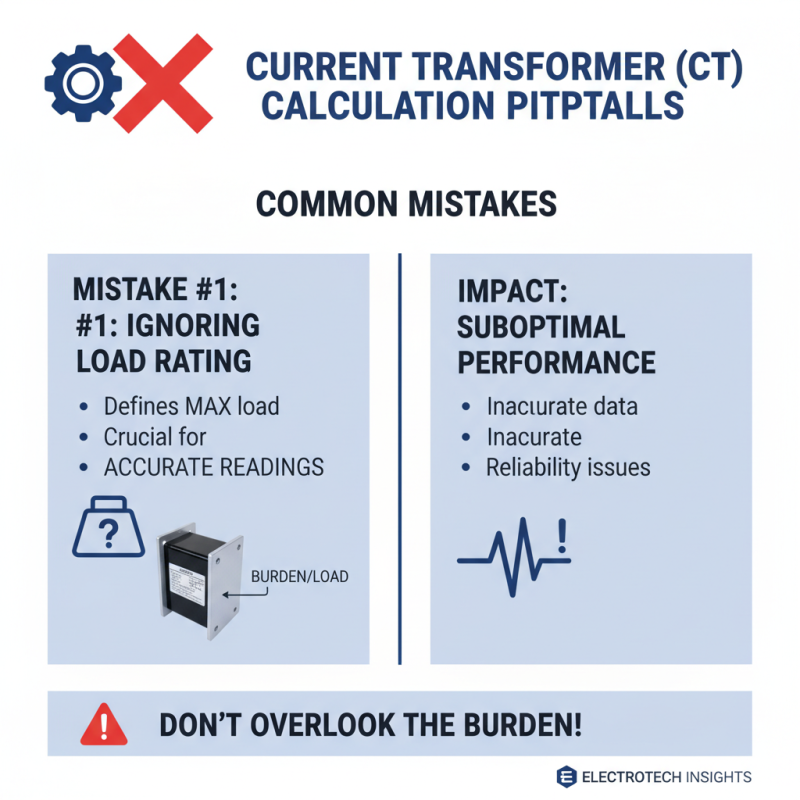
Common Mistakes to Avoid in Ct Calculation
Calculating current transformer (CT) parameters can be tricky. Many engineers make mistakes in their calculations, leading to suboptimal performance. One common mistake is ignoring the burden rating. This rating defines the maximum load the CT can handle. If this is overlooked, it may lead to inaccurate readings.
Another frequent error lies in the misinterpretation of sensor placement. The location of CTs affects measurement accuracy. Placing them too far from the load can result in notable discrepancies. Additionally, using scatter plots to represent data can sometimes mislead users. Simple graphs may provide clearer insights than complex ones.
Lastly, not accounting for temperature variations is a blunder. These variations can alter the resistance of components. Calculating CT based on nominal conditions may not yield real-world accuracy. Engineers should revisit their calculations frequently, ensuring they reflect changing conditions. Being aware of these pitfalls can significantly improve CT performance.